Thursday 26 March 2015

brain wave controled robot with mindwave headset

 brainwave controled robot

In this tutorial we discuss about how to control ur robot with ur brain
 components need 
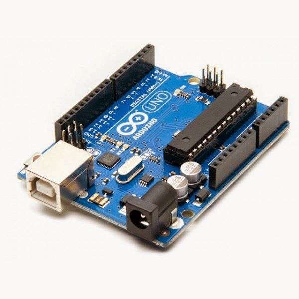
  • arduino board (i used arduino uno)
  • driver ic (l293d)
  • mind wave head set
  • dc motor
  • battery
  • robot chasis
  • pc or laptop(must have bluetooth)
software needed
  • arduino ide
  • mindwave mobile
  • communication bridge
steps,,,
  • install mindwave mobile on your pc
  • install arduino ide
make the body of robot


the green coloured board is the motor driver module ,u can buy it as it is or make this with the l293d 

connect the driver with the 9,10,11,12 pins of arduino 


now your robot is ready , 
now you can control your robot with your attention,,,!!!!! is it cool?????
for that u want the mindwave headset


         switch on ur head set and pair it with ur computer or laptop, the name of the device is mindwavemobile
  • open mind wave mobile on your pc
then u will get a window like this

select brainwave visualiser


make sure ur headset is turned on,, ten place it on ur head
then u can see ur attention level and meditation level
                              according to this attention level u can control ur robot speed,,
more your attention more your speed.
                       for that open arduino ide and paste the code below
int i;
int x;
void setup() { 
 pinMode(13,OUTPUT);
  pinMode(9, OUTPUT);   
pinMode(10,OUTPUT);
pinMode(11,OUTPUT);
pinMode(12,OUTPUT);
Serial.begin(9600);

}
void loop() 

{ if(Serial.available())
{
  x=Serial.read();
if(x<30)
{
for(i=255;i>4;i--)
{digitalWrite(13,LOW);
  delay(10);
   analogWrite(10,i);
   analogWrite(11,i);
}
}
   if(x>30)
{
for(i=5;i<256;i++)
{digitalWrite(13,LOW);
  delay(10);
   analogWrite(10,i);
   analogWrite(11,i);
}}
}}

connect arduino with your pc
upload this sketch to arduino board

after this open the communication bridge ,,

select ports for ur neurosky and arduino.you can find the ports from the device manager

click done .
now u can see ur robot speed is changing according to your attention level.
u can see the graphical representation also.
 now start fighting with your friends,,, check who have more attention.


Wednesday 19 November 2014

light intensity sensor using arduino

 * led will glow according to the intensity of light
components required
  • arduino uno
  • ldr
  • led
  • 10k resistor
  • wires
code


int sensorPin = A0;  
int ledPin = 13; 
int ledPin2 = 12;
int ledPin3= 11;
int ledPin4= 10;
int p = 0; 

void setup() {
  // declare the ledPin as an OUTPUT:
  Serial.begin(9600);
  pinMode(ledPin, OUTPUT);  
  pinMode(ledPin2, OUTPUT);
  pinMode(ledPin3,OUTPUT);
  pinMode(ledPin4,OUTPUT);
}

void loop() {
  // read the value from the sensor:
  p = analogRead(sensorPin);    
  // turn the ledPin on
  Serial.println(p);
if(p<820) 
  {
    digitalWrite(ledPin,p);
    digitalWrite(ledPin3,HIGH);
    digitalWrite(ledPin2, HIGH);
    digitalWrite(ledPin4,HIGH);
  }
  else
  {
   
    
    digitalWrite(ledPin, LOW);
    digitalWrite(ledPin3,HIGH);
    digitalWrite(ledPin4,HIGH);}
    if(p<850) //
    { }
    
    else
    { digitalWrite(ledPin3,LOW);
    digitalWrite(ledPin2, LOW);
    digitalWrite(ledPin, LOW);
    digitalWrite(ledPin4,HIGH);
    
 
  }
  if(p>870)
  {digitalWrite(ledPin4,LOW);
  digitalWrite(ledPin,LOW);
  }
}
  
connections
  • connect the led to the arduino board pins(13,12,11,10)
  • connect a 10 k resistor in series with the ldr,
  • connect the free end of resistor to the +5v pin of arduino
  • connect the free end of ldr to ground
  • connect the a0 pin to the ldr 
  • connect all the -ve terminal of led to ground
  • connect arduin to pc 
  • run the code


 TIP:- u can change the values according to ur surroundings
       :- open serial monitor for viewing the ldr values.( tools->serial monitor)

Saturday 15 November 2014

simple 7 segment display driver using arduino uno

simple 7 segment display driver using arduino uno
                  Here is a simple code for arduino for driving a 7 segment display.
                     
     arduino 

                                                                                                      disply
   
                          code


            int timer = 500;           // The higher the number, the slower the timing.

void setup() {
  // use a for loop to initialize each pin as an output:
  for (int thisPin = 0; thisPin < 14; thisPin++)  {
    pinMode(thisPin, OUTPUT);    
  }
}

void loop() {
  // loop from the lowest pin to the highest:
  for (int thisPin = 0; thisPin < 14; thisPin++) {
    // turn the pin on:
    digitalWrite(thisPin, HIGH);
    delay(timer);                
    // turn the pin off:
    digitalWrite(thisPin, LOW);
 delay(timer);  
  }

  // loop from the highest pin to the lowest:
  for (int thisPin = 7; thisPin >= 2; thisPin--) {
    // turn the pin on:
    digitalWrite(thisPin, HIGH);
    delay(timer);
    // turn the pin off:
    digitalWrite(thisPin, LOW);
  }
}

Here this code uses for loop for the selection of o/p pins and also for the state of each pin
steps

  • connect the ground and vcc of the display to the grnd and the +5v pin of arduino respectively.
  • connect the a,b,c,d,e,f, pin of ur display to the output pins(1-13) of arduino. ( u can connect it in any order as u like)
  • connect ur arduino to ur lap or pc
  • coppy the lnk above and paste it to the arduino Ide
  • upload the programme 

Friday 24 October 2014

flex sensor with aurdino

 flex sensor with  aurdinoundefined
On this tutorial, we will use the Arduino to read a flex sensor. The flex sensor is a device that changes its resistance proportional to its form, like this:
If the sensor is straight, it outputs 30k, it is flexed, 50k. With an Arduino board, make this circuit:
The resistor makes a voltage divider to make the reading possible. The analog input A0 is our signal.
Open the Arduino IDE and upload the following code. This code shows how many degrees the sensor is flexed.
// Flex sensor test program
// Mike Grusin, SFE, 2011
// This program is free, use it however you wish!
// HARDWARE:
// Make the following connections between the Arduino and the flex sensor
// Note that the flex sensor pins are interchangeable
// Sensor pin - GND
// Sensor pin - Analog In 0, with 10K resistor to +5V
// INSTRUCTIONS:
// Upload this sketch to your Arduino, then activate the Serial Monitor
// (set the Serial Monitor to 9600 baud)
void setup()
{
    // initialize serial communications
    Serial.begin(9600); 
}
void loop()
{
    int sensor, degrees;

    // read the voltage from the voltage divider (sensor plus resistor)
    sensor = analogRead(0);

    // convert the voltage reading to inches
    // the first two numbers are the sensor values for straight (768) and bent (853)
    // the second two numbers are the degree readings we'll map that to (0 to 90 degrees)
degrees = map(sensor, 768, 853, 0, 90);
    // note that the above numbers are ideal, your sensor's values will vary
    // to improve the accuracy, run the program, note your sensor's analog values
    // when it's straight and bent, and insert those values into the above function.

    // print out the result
    Serial.print("analog input: ");
    Serial.print(sensor,DEC);
    Serial.print(" degrees: ");
    Serial.println(degrees,DEC);

    // pause before taking the next reading
    delay(100); 
}
Upload the code and open the serial monitor to see the results.
That's it!

Tuesday 14 October 2014

Simple Mobile Jammer

Simple Mobile Jammer Circuit Diagram:

Mobile Jammer Circuit Diagram
Simple Mobile Jammer Circuit Diagram

Cell Phone Jammer Circuit Explanation:

  • If you understand the above circuit, this circuit analysis is simple and easy. For any jammer circuit, remember that there are three main important circuits. When they are combined together, the output of that circuit will work as a jammer. The three circuits are
    1. RF amplifier.
    2. Voltage controlled oscillator.
    3. Tuning circuit.
  • So the transistor Q1, capacitors C4 & C5 and resistor R1 constitute the RF amplifier circuit. This will amplify the signal generated by the tuned circuit. The amplification signal is given to the antenna through C6 capacitor. Capacitor C6 will remove the DC and allow only the AC signal which is transmitted in the air.
  • When the transistor Q1 is turned ON, the tuned circuit at the collector will get turned ON. The tuned circuit consists of capacitor C1 and inductor L1. This tuned circuit will act as an oscillator with zero resistance.
  • This oscillator or tuned circuit will produce the very high frequency with minimum damping. The both inductor and capacitor of tuned circuit will oscillate at its resonating frequency.
  • The tuned circuit operation is very simple and easy to understand. When the circuit gets ON, the voltage is stored by the capacitor according to its capacity. The main function of capacitor is to store electric energy. Once the capacitor is completely charged, it will allow the charge to flow through inductor. We know that inductor is used to store magnetic energy. When the current is flowing across the inductor, it will store the magnetic energy by this voltage across the capacitor and will get decreased, at some point complete magnetic energy is stored by inductor and the charge or voltage across the capacitor will be zero. The magnetic charge through the inductor will decreased and the current will charge the capacitor in opposite or reverse polarity manner. Again after some period of time, capacitor will get completely charged and magnetic energy across the inductor will be completely zero. Again the capacitor will give charge to the inductor and becomes zero. After some time, inductor will give charge to capacitor and become zero and they will oscillate and generate the frequency.
  • This circle run upto the internal resistance is generated and oscillations will get stop. RF amplifier feed is given through the capacitor C5 to the collector terminal before C6 for gain or like a boost signal to the tuned circuit signal. The capacitors C2 and C3 are used for generating the noise for the frequency generated by the tuned circuit. Capacitors C2 and C3 will generate the electronic pulses in some random fashion (technically called noise).
  • The feedback back or boost given by the RF amplifier, frequency generated by the tuned circuit, the noise signal generated by the capacitors C2 and C3 will be combined, amplified and transmitted to the air.
  • Cell phone works at the frequency of 450 MHz frequency. To block this 450MHz frequency, we also need to generate 450Mhz frequency with some noise which will act as simple blocking signal, because cell phone receiver will not be able to understand to which signal it has been received. By this, we can able to block the cell phone signal from reaching the cell phones.
  • So here in the above circuit, we generated the 450 MHz frequency to block the actual cell phone signal. That’s what the above circuit will act as a jammer for blocking the actual signal.

Quantum mechanics to charge your laptop

Quantum mechanics to charge your laptop? FIU prof is on it

Top scientists from UC Berkeley and MIT found the expertise they lacked at FIU. They invited Sakhrat Khizroev, a professor with appointments in both medicine and engineering, to help them conduct research as part of their NSF-funded Center for Energy Efficient Electronics Science.
The group is looking to cut the cord, literally, by finding ways to efficiently power computers of the future. Energy consumption from laptops, huge data centers and every other Internet-connected electronic device is rising exponentially and could impact available resources down the road. To reverse this energy-guzzling trend, the Berkeley-based center is investigating the use of revolutionary nanotechnology—the manipulation of matter on an atomic, molecular and supramolecular scale—to create endlessly charged atomic batteries that could supplant our reliance on the plug.
“I am honored,” says Khizroev of his inclusion on the elite team. His peers tapped him because they needed an expert in something called “the magnetic spin of electrons and spintronic devices,” as he explains it.
Khizroev
In the spin lab: Sakhrat Khizroev, left, with researcher Rakesh Guduru
Discovered in the 1980s, spintronics harnesses the magnetism and constant gyroscopic spin of electrons to process data. With a naturally negative charge, electrons are subatomic particles that orbit around an atom’s nucleus like the rings around Saturn, and their magnetic energy could provide theoretically limitless power.
Such continuous energy would not just solve our mundane (and incessant) need to recharge tablets and cell phones, it could also move computing to the next level. “You can say that our research is a stepping stone towards achieving a holy grail of computer processing known as quantum computing,” says Khizroev of the physics that would allow the crunching of numbers at breathtaking speeds but which currently is constrained by huge energy requirements. “Then anything is possible,” he says. “Eventually it will happen, but we’re not there yet.”
Quantum computing is so complicated that it exists mostly as a theory. That could change with the research taking place in the Berkeley center and in FIU’s labs. In 2013 Khizroev published research on the discovery of the world’s smallest version of an energy-efficient information processing technique, called spin-transfer torque. 
Jeffrey Bokor, deputy director of the center and leader of the nanomagnetics team, calls Khizroev’s work “pioneering.” It is the application of Khizroev’s findings, Boker explains, that will be explored by the center’s researchers as they consider new concepts for computers powered entirely by magnetic devices.
These atomic processes (none of which involves the chain reaction on which nuclear power plants rely) are mind-boggling to any non-engineer, and even many engineers remain skeptical of their application. Like his colleagues at the center, Khizroev has no doubts.
“Nanotechnology is everywhere in the future,” predicts Khizroev, who holds more than 30 patents and is a fellow of the National Academy of Inventors.
At FIU he dedicates 80 percent of his time to medicine and has published academic papers on nanomedicine to treat HIV and ovarian cancer. He is also pioneering the use of nanoparticles to treat brain disorders such as Parkinson’s disease.
But that work took a temporary backseat recently when Khizroev returned to his roots as a physicist and electrical engineer when he invited FIU graduate students Ali Hadjikhani and Mark Stone to travel with him to the Berkeley center for some brainstorming.
“I did not completely forget my old expertise,” Khizroev says, “but it’s more like a hobby. A side project.” 
Hobbyist or not, he remains among the world’s elite researchers seeking novel ways to power the future. 

Saturday 4 October 2014

Accelerometer

Accelerometer

It’s an electromechanical device that measures acceleration and tilt angles by using the MEMS (Micro Electro Mechanical Systems) technology, where acceleration is the rate of change of velocity with respect to the time. Acceleration forces may be Static or Dynamic depending upon the way one uses the accelerometer. The change in the acceleration leads to change in the voltage output of the accelerometer.

Types of accelerometers:

Hall Effect Accelerometers:
The alternating magnetic fields are sensed with respective to different motions and then the corresponding motion is converted into an electric signal.
Piezo Electric Accelerometers:
The piezoelectric crystals have the property of generating voltages when they are pressurized. This property is induced in these type of accelerometers to sense the motion and produce corresponding signals.
Capacitive Accelerometers:
The two micro structures placed nearby, induces a capacitive value between them whose capacitance value changes according to the motion. So by converting the capacitance value into voltage, the motion can be sensed.
Uses of Accelerometers:
Accelerometers have been extensively used in the field of Automation and Robotics. For example, they are embedded inside the latest versions of laptops (Apple) for preventing the hard disk being damaged by unexpected free fall of them. So basically in these laptops, the hard disk gets switched off automatically whenever accelerometer senses a free fall.
They are also used in Humanoids along with gyro sensors for maintaining the center of gravity positioned in canter of the body. Accelerometers detect vibrations and can be used for testing car engine. They can sense the car crashes and push out the airbags at the right time saving the lives of people in the car.